2024-01-23
Network, structure, setup
The following provides network setup diagrams and guidelines for configuring CCBootCloud servers and clients, optimizing performance through NIC teaming and switch configurations to ensure efficient data throughput
- We all have set up the CCBootCloud server and clients many times but we did not get it right the first time. So, refer to our simple layout diagram for CCBootCloud to set it up and network right at once.
- You can use the following layouts as your base to set up your network for CCBootCloud.
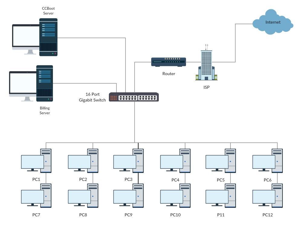
- CCBootCloud server with just 1 NIC (Total 1.0 Gbps).
Figure 1
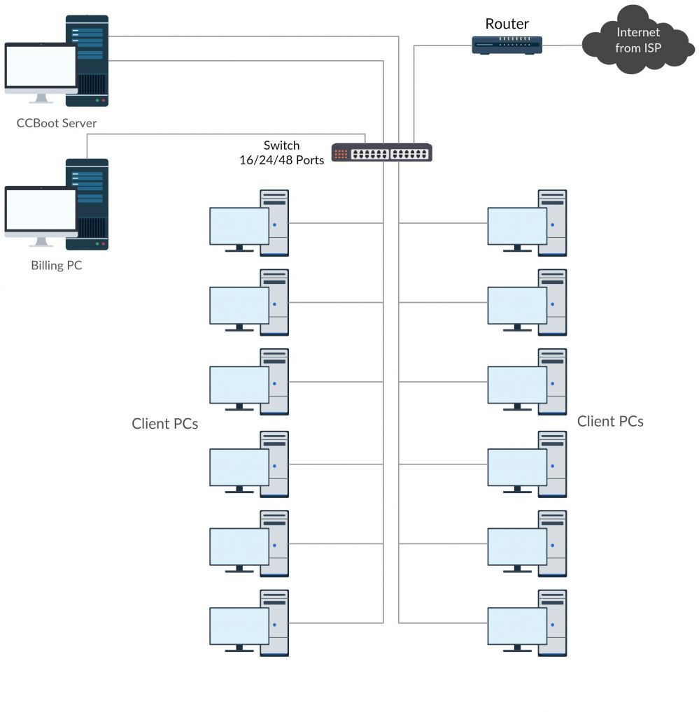
- CCBootCloud server with 2 NICs in teaming (Total 2.0 Gbps).
Figure 2
- CCBootCloud server with 4 NICs in teaming (Total 4.0 Gbps)
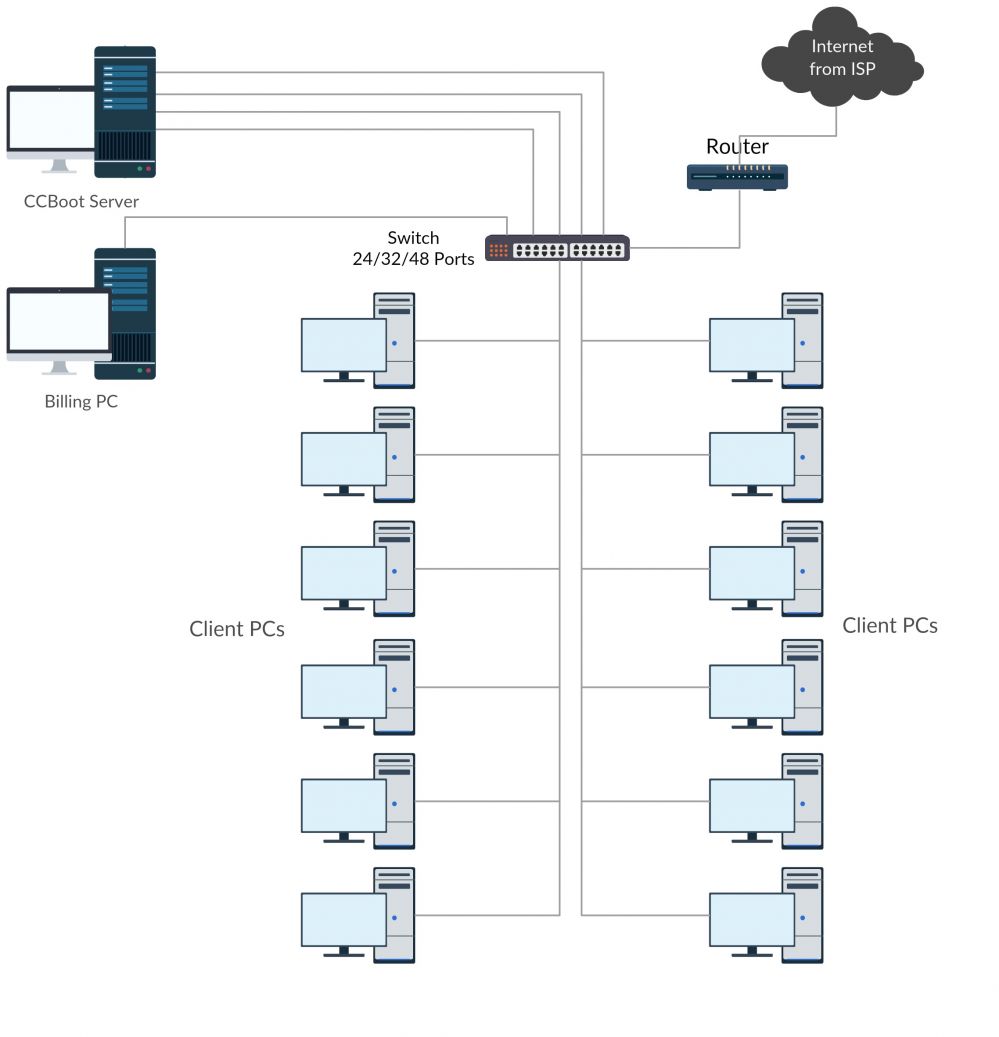
Figure 3
- CCBootCloud server with 2 switches and 4 NICs in teaming (Total 4.0 Gbps)
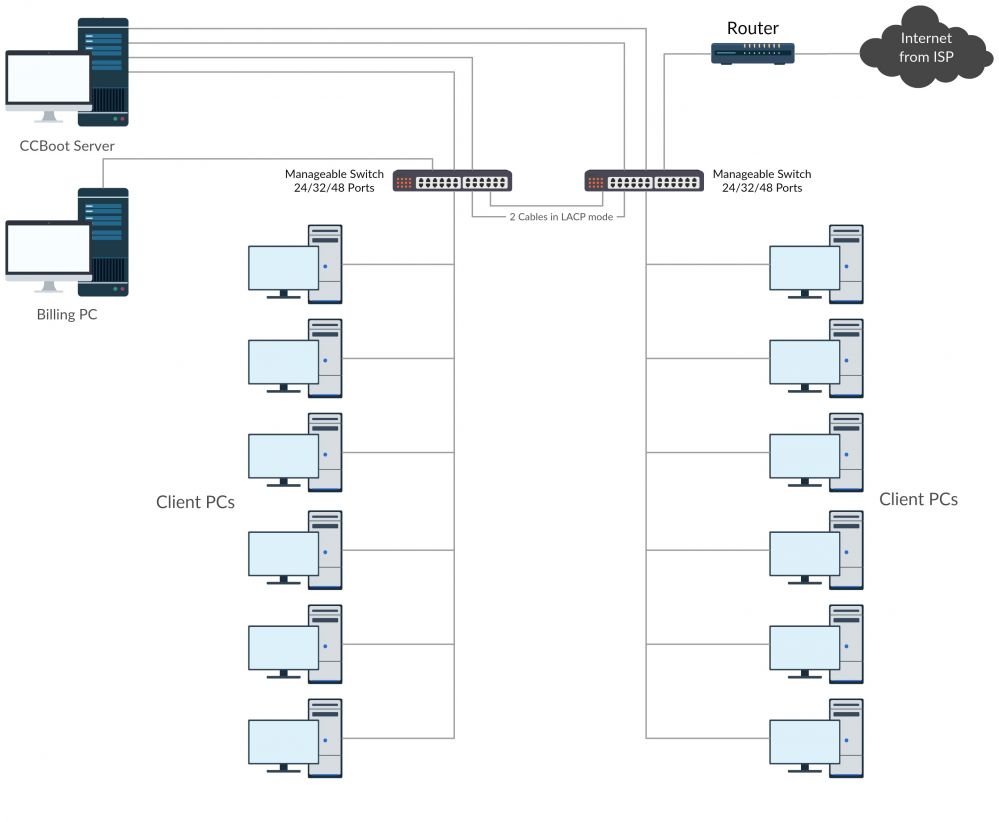
Figure 4
2 cables in LACP mode allows each switch user to be able to share 4.0 Gbps of bandwidth between 2 switches. DO NOT use more than 1 cable without LACP between the switches.
You can use 1 cable between the switches if you do not have a manageable switch however max usable bandwidth for clients will be 3.0 Gbps only.
- Two CCBootCloud servers with 2 switches with 4 NICs teaming on each server.
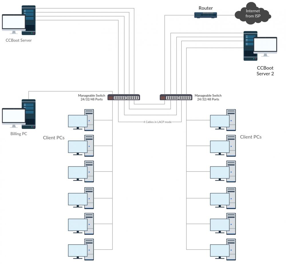
DO NOT use more than 1 cable without LACP between the switches.
Two CCBootCloud servers with 2 switches
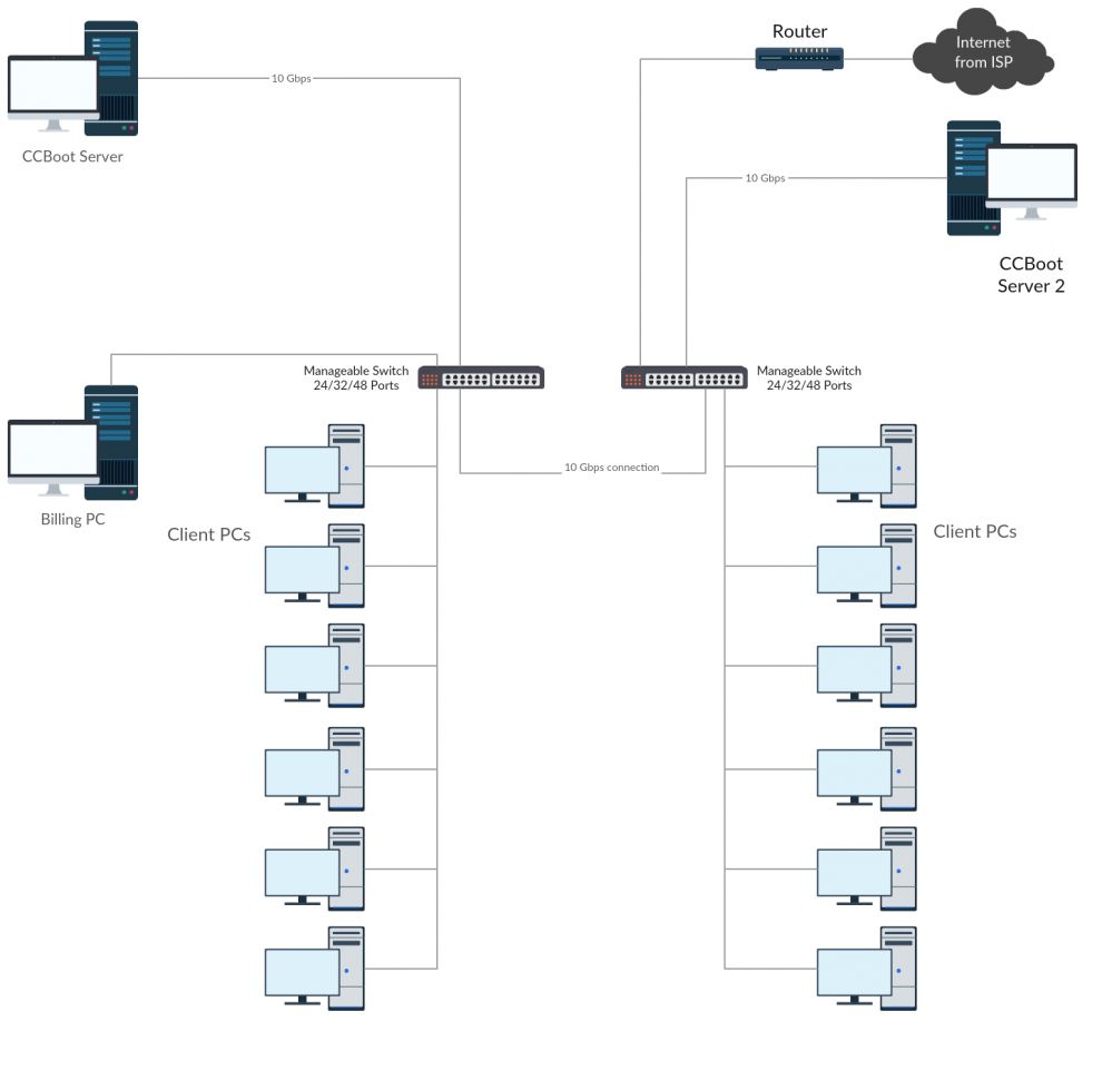
- Two CCBootCloud servers with 2 switches with 10 Gbps NICs each server.
Figure 6
One CCBootCloud server with 4 switches
- Server Connectivity: The CCBoot server is equipped with four 10Gbps SFP+ ports, with each port directly connected to a dedicated switch.
- Switch Interconnectivity: The switches are daisy-chained (or interconnected) using standard RJ45 Ethernet cables. The link speed between the switches is determined by the maximum capacity of their respective copper ports.
- Client Connectivity: Client PCs are distributed across the switches, ensuring every client has high-speed, low-latency access to the server’s 10Gbps bandwidth pool. (Figure 7)
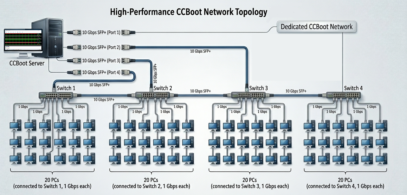
Figure 7